When constructing the Empire State Building in 1930, engineers found that the heavy non-armored electrical cable installed in vertical raceways or risers imposed excessive strain on terminations, panels or other connected devices. In all, electricians installed a staggering 2,500,000 feet of electrical wire to convey the 40,000,000-kilowatt hours used by the building and its tenants annually. To answer this challenge of how to safely install vertical conduit raceways in a 102-story building, the engineers relied on cast iron and hardwood cable supports. This year, as the Empire State Building celebrates the 88th anniversary of its groundbreaking, many of those same cable supports remain in service.
Cable supports are one of the electrical industry’s unsung heroes. Designed specifically to support cables in vertical raceways and eliminate strain on terminations, the supports can make the difference between being connected or disconnected in multi-story buildings. When installed, they provide end-users with enhanced safety and lower maintenance.
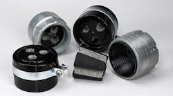
O-Z/Gedney Cable Supports
Cable supports must provide support to the heavy cable without damaging the insulation or excessively reducing the amount of insulation over time, so the materials that are used and their engineering are important. Impregnated hardwood or Bakelite wedging plugs are standards. Iron or Bakelite bodies, combined with sealing compound, are also used for certain applications since they can include a weatherproof seal and provide ventilation at the top of the conduit riser. Proper venting can reduce the temperature in a riser by up to 20° F.
TYPES OF CABLE SUPPORTS
Cable support design is deceptively simple. Essentially, cable support bodies are threaded to conduit or rest on existing bushing atop any conduit raceway in which non-armored cables pass through. The one-piece or multiple segment wedging plug is inserted into the cable support body. The edging plug exerts pressure around the cable, providing holding force of that required by code.
There are two basic types of cable supports: the one-piece plug and the multiple segment plug. The one-piece has a single wedging plug with a groove for each wire. It is ideal for all types of non-armored cables 600 Volts or less, plus it is considered the easiest to install. In contrast, the multiple segment version has a wedging plug constructed so that each cable is supported between grooves in adjacent segments. This uniform pressure distribution is required by the softer types of insulations frequently used at higher voltages. Some supports line cable grooves with coarse grain grit to improve holding power without damaging the jacket or insulation on the cable. In both cases, either one-piece or multiple segment, it is good practice to space conduits about 1/2" or more further than normal to accommodate the cable support body.
GETTING A GRIP ON THE CODE
The National Electric Code (NEC) calls out specific installation methods for long vertical runs. NEC Article 300.19 (Supporting conductors in vertical raceways) states that cable support is needed at the top of a long raceway, with intermediate supports installed at specified lengths according to a formula based on the size of the wire, some as frequently as every 40 feet.
NEC® Table 300.19(A) shown below provides the distances required between supports for the conductors.
Let’s look at an example. In a ten story building with conduit runs from the basement to the top floor with raceway containing 4/0 copper conductors, the unsupported copper cable length cannot exceed 80 feet. The heavier the wire, the shorter the unsupported cable length. According to the NEC, the only exception is “Steel wire armor cable shall be supported at the top of the riser with a cable support that clamps the steel wire armor. A safety device shall be permitted at the lower end of the riser to hold the cable in the event there is slippage of the cable in the wire-armored cable support. Additional wedge-type supports shall be permitted to relieve the strain on the equipment terminals caused by expansion of the cable under load.”
The NEC also lists these four ways to support cable.
- By clamping devices constructed of or employing insulating wedges inserted in the ends of the raceways. Where clamping of insulation does not adequately support the cable, the conductor also shall be clamped.
- By inserting boxes at the required intervals in which insulating supports are installed and secured in an approved manner to withstand the weight of the conductors attached thereto, the boxes being provided with covers.
- In junction boxes, by deflecting the cables not less than 90 degrees and carrying them horizontally to a distance not less than twice the diameter of the cable, the cables being carried on two or more insulating supports and additionally secured thereto by tie wires if desired. Where this method is used, cables shall be supported at intervals not greater than 20 percent of those mentioned in the preceding tabulation.
- By other approved means.
There is a mistaken belief that the NEC does not come into play on low voltage installations, however, there is no exemption whatsoever for voltage. NEC 300.19 applies to all installations, high or low voltage.
Additionally, there is a misconception that the use of wire mesh grips or even sheet rubber wrapped around conductors and tied off in the box is enough to satisfy the code. Neither approach meets NEC Article 300.19 for supporting conductors in long vertical raceways in situations outlined in the table. While wire mesh grips are very useful in shorter runs they have no place in applications outlined in the NEC chart.
SPECIFYING CABLE SUPPORTS
When ordering a cable support, manufacturers ask the purchaser that they specify the number of conductors being supported and to provide each conductor’s outside diameter (OD), in addition to the conduit trade size, voltage, and dry or wet location. Slight variations in cable OD can render a support plug either too large or too small. Jacket sizes, in particular, can fluctuate - so can stranded wire depending on things like the number of strands, amount of twist and manufacturing processes. For this reason it is recommended that the person doing the ordering, whether it is the purchaser, project manager or lead electrician, use a digital micrometer or calipers to accurately measure the cable’s OD.
Another problem that occurs in the field is when an electrician, pressed for time to complete a job, upsizes the cable being installed to one that is available onsite, rather than waiting for the right-sized cable to be delivered. Needless to say, the factory-drilled supports are now too small for the cable. Ordering and installing only the cable support body prior to wire pulling can alleviate the problem. The other part of the support, the wedging plug, can be ordered later.
RETROFIT APPLICATIONS
When electricians hear the word “retrofit” they assume they are replacing an existing worn part for a new one. However, in the context of cable supports, “retrofit” refers to specialized supports that are installed after conductors are pulled and terminated, not before. The support isn’t being replaced since it wasn’t there in the first place.
What situation would call for a retrofit cable support? Let’s look at the example of an inspector or Authority Having Jurisdiction (AHJ) conducting a final inspection of a high-rise who finds a code violation involving the vertical raceways, specifically the lack of cable supports. Or where the lead electrician finds sub-par work done by an apprentice who installed wire mesh grips instead of supports. These types of problems happen on jobsites, as every experienced electrician knows. Because the split body of a retrofit-style support rests on an existing bushing atop the conduit raceway it is possible to use it where cables are already installed. The two halves of the body are placed around the cables, seated on the existing bushing, and securely held together by the steel band set in a groove around the body. The plug is then wedged between the cables and the job is done. Problem solved.
CONCLUSION
Unfortunately, there is no shortage of confusion when it comes to cable support requirements. With so much at stake it is the responsibility of the electrician to fully understand NEC Article 300.19 compliance and best industry practices, as well as the difference in cable support types.


