Latest from Simulation/IT
The Revolution of Simulation Software Development
Forging simulation software is no longer a niche application used only by top-level engineers at advanced forge shops. Having established its effectiveness over many years, it is used now to generate forging simulations quickly and accurately. Even the most basic forge shops run simulations prior to die production to ensure that the material will flow correctly, to determine the load required for forging, and to optimize tool life.
However as the use of these most basic functions of simulation software have become commonplace, users at many forge plants continue to demand more features and functionality for specific forging problems as well as faster and more flexible results. To keep up with the industry’s increasing demands, most simulation software has evolved by adding new features and functionality to the old program core that may have been unchanged for years. Most of the recent developments of simulation software have concentrated on extending areas of implementation rather than increasing the performance of the core program itself.
This was exactly the situation QuantorForm Ltd. recognized a few years ago. The popular QForm program was reliable and accurate but it was increasingly difficult to add new features demanded by users around the world because the program core that had been used for years was growing obsolete.
In 2008 a group of energetic programmers that had joined the development team staged something of a revolution: they insisted that the only way to meet the demands of the industry and move successfully into the future was to scrap the old code and develop a completely new program. The founders of the company, who had developed the original commercial code back in the early 1990s, recognized the wisdom in this strategy and made the radical decision to stop development of the existing program.
Then, the company began a new project to develop a completely new program using the most modern programming techniques, incorporating all of the knowledge gained from 20 years of experience in forging simulation software development and implementation. It was a very risky decision, because even for such an experienced team it was anticipated that this task would take several years, and improvements to the existing QForm program in use at hundreds of companies around the world would be suspended, with an unpredictable impact on the company’s market position.
Forging engineers have a lot on their plates these days and they don’t have the luxury of being able to spend hours tweaking a simulation to get the required results. Their time is valuable and they demand a program that allows them to set up simulations quickly that will give them the most accurate results. They want faster simulation speeds and more interface flexibility so that experimenting with various scenarios is quick, fluid and intuitive.
Also, existing QForm users wanted to be sure that the new program was compatible with the old version and retained the ease of use and familiar features of the previous version of the software such as simulation of both 2D and 3D problems, detection of laps, flow through, and non-fill defects as well as full tool simulation capabilities including die stress and die wear.
The effectiveness of simulation software requires much more than just the capability to treat large finite-element models. A critical balance between power, flexibility, ease of use and speed must be met. The development team’s objective was to meet the demands of industrial and academic users with a new program that offered a well-balanced combination of high performance, flexibility, speed, and accuracy with a quick learning curve for new, inexperienced users, while also allowing for profound analysis capabilities for the most advanced users and researchers.
The Mesh at the Core
The finite element mesh (F.E.M.) is the core of any modern forging simulation software so the programming of the meshing algorithms for the new program required special attention. The fundamentals of the meshing techniques used in the previous versions of QForm were based on the idea of creating the meshes separately on the surface of the deformed body and in its volume. But so much had been learned in the past 20 years of practical implementation that would now need to be applied to the new meshing techniques to make it able to work with the most complicated laps and burrs that may occur as a result of deformation.
The ideal mesh should be non-uniform and self-generating to ensure a high degree of accuracy and ease of use for novice users, and still allow advanced users complete access ‘under the hood’ to control meshing parameters, to modify the mesh any way they want.
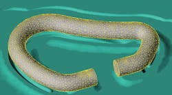
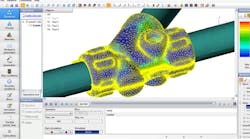
The speed of the new mesh generation algorithm was also a major consideration. In QForm7 themesh is generated through the entire body and surface and the program automatically chooses which elements and nodes can be kept from the previously calculated mesh that still complies with mesh quality requirements. This process considerably speeds up the mesh generation. The surface mesh on the tool is a quadratic mesh that is able to curve to represent the geometry more accurately, and the tetrahedral volume mesh is regenerated throughout the course of the simulation. This allows for mechanically coupled simulations where the deformation of the die during the forming stroke affects the material flow. High-level users can optimize the mesh adaptation and density easily for any combination of velocity, stress or temperature.
In order to ensure seamless integration between 2D and 3D simulations it was decided that a single meshing algorithm would generate mesh for both 2D and 3D simulations. This will also streamline future development because the same interface and algorithms would be used for both modes, so features added to one platform will be applied to the other.
The team developed a completely new interface, a revolutionary new architecture and data structure, and a new flexible graphical interface, all written with the most modern programming techniques. Many fundamentals like discretization algorithms and numerical methods were redeveloped from scratch.
The new program runs significantly faster thanks to advanced algorithms and full parallelization of the computations.
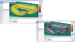
The new architecture allows the simulation core to run independently from the interface. This makes the graphical interface extremely powerful and flexible. Even while the simulation is still running the user can play the results forward and backward, make crosscuts, measurements, create graphs, and any other kind of analysis. The new data structure efficiently writes and retrieves huge amounts of data, which permits storage of every step of the simulation results. This means that the playback is smooth at 25 frames/second, and the results are extremely accurate and nearly indistinguishable from the actual forging.
The Question of Reliability
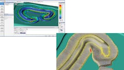
The new data structure also means that a lot of analysis can be done in the post-processor so users can test different scenarios without having to re-run the simulation. Even for forgings when the surface collapses, creating severe laps, the simulation runs to completion and the results are very accurate. With QForm7 users can accurately trace tracked points and flow lines forward and backward, produce graphs and numerical data from tracked points, modify the fit of inserts or shrink rings in tool simulations, and calculate user-defined functions, all in just in few seconds from the post processor. The sophisticated mesh generation algorithms can easily handle formation of laps and folds, intensive shearing deformation, multiple bodies like bimetallic billets or composites as well as pre-stressed die assemblies.
QForm7 features new algorithms for solving coupled mechanical and thermal problems where the temperature and deformation of the dies are calculated concurrently with the simulation. It has both explicit and implicit solvers as well as elastic-visco-plastic formulation that allow for simulation of residual stresses and distortion. These new methods are so effective that the entire press structure can be included in a simulation coupled both thermally and mechanically with the deformation of the billet and the dies.
For advanced users, QForm7 allows easy programming and seamless display of User Defined Variables and Functions. Any kind of model like flow stress data, ductile fracture, or microstructure evolution can be added to the program easily with user-defined functions (UDFs) that can be calculated during the simulation itself or in the post processor, either for each instant of time or for the whole history of the process development. To implement UDF a new method of Just-In-Time (JIT) compilation has been implemented and anyone who has ever tried to do this on other software platforms will appreciate that no compiler is required and these functions are performed at the same speed as the main code.
The results of the revolution of simulation software development at QuantorForm Ltd. have been remarkable. The new QForm7 program is incredibly fast and very accurate, and even novice users will easily get accurate results. Our benchmark tests have shown some QForm7 simulations run up to 40 times faster than in the previous version.
But, what really is exciting is the flexibility of the new program. All data can be imported and exported into/from other programs, and the user has complete control over most functions via User Defined Functions.
QForm7 is already in use at hundreds of companies around the world simulating processes, including: open- and closed-die forging, ring and wheel rolling, forming of porous materials, longitudinal and transversal rolling, reducer rolling, hydroforming, thick sheet metal forming, cross-wedge rolling, profile extrusion, fastener manufacturing and installation, and heat treating/microstructure analysis. With the power and flexibility now available in new F.E.M. software codes combined with the availability of inexpensive high-power multi-processor computers, the optimization of simulation software for metal forming processes is poised to grow exponentially into the next decade.
Tom Ellinghausen is the president of Forge Technology Inc., which supplies QForm software as well as forging presses, automation, furnaces, and preforming equipment to North American forgers. Contact him at [email protected], or visit www.ForgeTechnology.com.
