


Cross-wedge rolling (CWR) is one of the most efficient ways to manufacture axially symmetric parts in large scale and mass production. It combines economical use of material, high performance standards, and high process efficiency for forming precision products.

One restriction to CWR technology is the lack of ductility in some alloys, which can lead to a defect of axial cavity opening, known as the Mannesmann effect. Rolling of structural steels, and ductile series alloys based on copper, nickel, aluminum, and zirconium, can be done without complications1–3. The range of dimensions for parts used in manufacturing meets all industrial requirements: the diameter of 1 to 190 mm, length of 20 to 1000 mm.
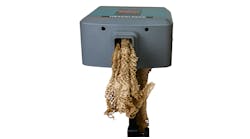
The CWR process also can be used effectively for producing surfaces (see Fig. 1) or spheres, or combined with a forging process to produce parts with an elongated axis, for example, automotive engine rods or Cardan shaft yokes4.
Expanding the scope of CWR — Warm rolling is a process that is carried out at lower heating temperatures (for steel it is 600-800°C.) As a result, energy is conserved, surface roughness is improved, and the precision of the finished forgings is enhanced. The disadvantage of this technology is that it reduces the resistance of the wedge tool and requires a more qualified specialist to design the tool.

The CWR process involves a reduction ratio from two to four. Conventional CWR technology is restricted by the reduction ratio δ = 2 for one cycle, decreasing by two times the diameter of the part during rolling. With a further increase in the reduction ratio the workpiece is ruptured into two parts due to excessive tensile forces.
The special design of the wedge tool can reduce the tensile forces and bring it to the maximum reduction ratio, δ = 4. The advantage of this technology is that it reduces the tool length, and therefore its cost, because it eliminates the need to carry out rolling in two setups. This technology is used in cases in which the difference in diameters of forgings is more than two.
The authors discovered the effect of welding in CWR operations5. If the outer surface of a wear sleeve blank is formed from another alloy, and then heated and the structure is laminated, deformation occurs at the contact surface on the workpiece and sleeve welding. The strength of the weld does not alter the preform.
This technology makes it possible to produce laminar shafts, wherein there can be several outer layers. As a result, there is a possibility of manufacturing products with new properties, such as wear-resistant or corrosion-resistant outer surfaces and parts with high fatigue strength. The weld is not destroyed if the rolled workpiece (see Fig. 2a) is further stamped (see Fig. 2b) and shaped to produce a solid forging with the outer surface of the other alloy.
This is a new field of application for forgings with critical properties. If the workpiece is in the form of a tube with two layers, with a welded stub inserted, the hollow shaft is sealed (see Fig. 2c). As a result, it becomes possible to reduce the weight of a part for critical applications, such as in aircraft structures. When welding a homogenous alloy in CWR, a monolithic metal structure is formed at the contact points between the workpiece and the sleeve, i.e. the welding seam is not detected (see Fig. 2c.)
Backward CWR — If the inclined faces of the wedge tool are arranged opposite to each other, the process not only can reduce the diameter of the initial billet but in limited areas it can increase its diameter by 30-50%. The advantage of this method is the ability to use a blank diameter less than the maximum diameter of the product. This ensures reduction in compression, reduction of the length of the tool and, oddly enough, the reduction of metal consumption due to the reduced size of sink marks on the forging’s ends.
Parallel CWR — Unlike traditional CWR, in this version rolling is carried out at the same time by four or six wedges, rather than two. As a result, the length of the tool is significantly reduced, which in addition to reducing the cost of the tool increases the productivity of the process and allows using cheaper and smaller mill.
The disadvantage of Parallel CWR technology is the need to attract a more qualified specialist to design the tools.
Reduced Consumption of Metal


The metal utilization rate in CWR metal forming processes ranges from 80 to 98%. But, the share of the cost of the metal panel to the main cost is quite high – about 80%. In this context, the task of conserving the metal during rolling is highly relevant.
Rolling twin forgings — During CWR segment rolling there is a greater loss of metal at the end section, where size determines the depth of the sink mark at the end of the workpiece, which is inevitably formed at its straight end. As a result, it is necessary to cut off the two waste ends of a forging.
If the CWR is designed to produce dual forgings (see Fig. 3), instead of the four waste ends there will be only two — halving the total metal loss. Additional savings are created by the fact that the initial billet is designed for the two parts, which reduces the number of blank cutting operations.
Reduced allowances of the rolled workpiece is achieved by increasing the accuracy of forgings, by increasing rigidity of rolling mills, by adjusting the distance between the tools at rolling, by preheating tools to stabilize thermal expansion of the mill stand, and by controlling the temperature of the workpiece.
Improving product quality — An important feature of the CWR process is the location of tensile stress in the axial area of the deformation zone, and the compression stress three to four times higher than the yield stress in the contact area between the workpiece and the tool. The latter, along with great accumulated strain, leads to the so-called "healing" of structural defects in the surface layers of metal forgings.
Therefore, fatigue strength of the products obtained by the panel formation is substantially higher than in the items produced by landing or turning. As such, the automotive ball pins formed with the panel structure (see Fig. 2) demonstrated increased fatigue strength during operation by 123% over the original.
Greater values for accumulated strains at CWR contribute to enhanced mechanical properties due to significant grain refinement of the metal. A technology for producing metal balls (see Fig. 4a) that includes continuous casting, straining of cast copper using ECAP, and subsequent CWR, has allowed a 200-times reduction of the grain size – from 1,000 to 5 μm (see Fig. 4b). As a result, it has provided essential enhancement to the quality of plated coating of integrated circuits for electronic engineering.
The surface roughness is achieved by creating optimal geometry of the wedge tool and it can reach its maximum value (Ra=1.25) at warm CWR.
The accuracy of the billet’s dimensions is improved by increasing of hardness of mill rolls, using of high-accuracy roller bearing in mill sliders, stabilizing the thermal state of the rolling stands, and monitoring billet heating temperature. The maximum accuracy achieved by warm CWR of billets with a diameter of 7 mm is ±7 μm. Precise proportioning of metal in a CWR billet allows qualitative filling-in of die impressions in a subsequent, flash-free stamping that is carried out without additional heating.
V.Y. Shchukin and G.V. Kozhevnikova, are affiliated with the Physical-Technical Institute of the National Academy of Sciences of Belarus, in Minsk.
References
1. Shchukin, V.Y., Kozhevnikova, G.V. "Cross-Wedge Rolling Theory, Technology and Equipment," Forge, June 2015.
2. Kozhevnikova, G.V., Shchukin V.Y. "Cross-Wedge Rolling Theory, Technology and Equipment," Industrial Heating, November 2014.
3. Kozhevnikovа, G.V., Cross-Wedge Rolling – Minsk: Belorusskaya Nauka, 2012. – 321 с.
4. Shchukin V.Y., Kozhevnikova G.V., "Technics and equipment of flat wedge cross-wedge rolling," Duanya Jishu. Forging & Stamping Technology 2009, vol.34, no.6, pp.4–7.
5. "Method of Manufacturing of the Axisymmetric Laminar Step Part", patent 13417, Republic of Belarus, IPC В21 H1/00. / V.Y. Shchukin, G.V. Kozhevnikova / Official Register / National Center of Intellectual Property – 2010, No.4, pp.74-75.


