Download this article in PDF format.
We are in the midst of a smart-metering revolution. Over the next five years, the global smart meter market is expected to grow tremendously. Smart metering has advantages for the utility provider and for the user. For the provider, it eliminates the resources required for an operator to make monthly visits to each meter location. The provider can remotely control the water/gas supply.
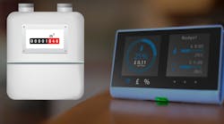
More importantly, the remotely collected data can be aggregated and analyzed in real time, which may help spot leakages, detect tampering, and provide other useful data analytics to reduce opex. The consumer will also have electronic access to his or her consumption data, leading to better resource management. Smart meters, in particular water and gas meters (Fig. 1), use wireless connectivity and are poised to move from wireless M-BUS or proprietary standards to 4G and 5G.
A common characteristic of these devices is remote operation for long periods of time, which is achieved using powerful primary, non-rechargeable batteries.
Lithium-thionyl-chloride batteries are often chosen for their high capacity. These batteries, although packing a charge of tens of ampere-hours (Ahr), under “old and cold” conditions, can release it only in trickle amounts, due to their increased impedance.
However, during wireless data transmission, the meter’s power amplifier (PA) requires peaks of current an order of magnitude higher than the battery can deliver.
In this design solution, we discuss the challenge of powering the PA. This solution is based on an efficient, low shutdown current and compact boost converter that delivers the required peak current with the help of a supercapacitor.
For the purpose of this case study, the PA works off a constant voltage of 4.1V. As seen in Fig. 2, the PA requires a current burst of 0.7 A for one second every six hours to transmit data. The rest of the time, the PA is shut down. This corresponds to an average current of 32 µA.
Powering the PA
A 3.5-V, D-cell lithium-thionyl-chloride battery can be used to power such a PA. This battery would have a 19-Ahr charge, which translates to 217 µA on average over a 10-year lifetime. Such a battery may have a worst-case (old and cold) impedance as high as 30 Ω. Accordingly, it can deliver at best 117 mA. To deliver 0.7 A, we need the help of another energy source like a supercapacitor, which can provide high-density capacitance in a compact volume and is ideally suited for burst energy.
A typical 10-F supercapacitor has a voltage rating of 2.7 V. Since the supercapacitor has to work in parallel with the 3.5-V D-cell lithium-thionyl-chloride battery, two capacitors in series are used to withstand the battery voltage.
Under an “old and cold” scenario, these two 10-F supercapacitors in series (5 F total) may derate down to as low as 2 F and 200 mΩ. This supercapacitor ensemble (C), charged with 3.5V and with a 200-mΩ equivalent series resistance (ESR), easily delivers 0.7 A. At the first order, the capacitor, loaded with I = 0.7 A for a time T = 1 sec should droop just about 350 mV (VDROOP = T × I/C) with an additional voltage drop across the ESR of about 140 mV.
The strategy then is to have the supercapacitor deliver current to the PA for 1 sec (1 sec × 0.7 A = 0.193 mAhr). During the subsequent six hours of shutdown, the supercapacitor is replenished by the battery. While many system designers use a supercapacitor to augment a primary cell battery, currently some battery vendors also provide a battery + supercapacitor combo in an industry-standard battery housing like say, D-cell.
PA Voltage Regulator
In Fig. 3, during the six hours of PA shutdown, the D-cell battery charges the supercapacitor C up to the D-cell voltage; for example, 3.5V. At the end of the charging cycle, there’s no further current exchange between the battery and the supercapacitor, and their voltages coincide. When the rising front of the PA current peak arrives, the supercapacitor provides the bulk of the energy, causing its voltage to sag. The boost voltage regulator boosts the sagging input voltage, providing a constant 4.1 V and 0.7 A to the PA with η = 95%.
The process of charge and discharge of the supercapacitor is outlined in detail with the aid of simulations in the following section.
The circuit in Fig. 3 is simulated and the resulting waveforms are shown in Fig. 4. The blue waveform is the PA current transmission pulse. The red waveform shows the boost converter input voltage going down from the 3.5-V primary cell voltage to 2.82V during the 0.7-A PA pulse (blue graph).
The corresponding input current, in green, starts at 0.9 A (PIN/VIN) and rises up to 1.4 A as the input voltage decreases, maintaining constant input power so as to supply the 0.7-A output current at 4. V.
Fig. 5 illustrates how most of the current pulse IIN (green trace) comes from the supercapacitor’s current ISUPERCAP (red), with minimal contribution to the input current from the battery. During the PA shutdown, the input current IIN is null and the battery current +IBATT (blue) recharges the capacitor (−ISUPERCAP).
With a 10-year lifetime requirement, it is extremely critical that the boost converter used doesn’t drain away the battery with its quiescent current, thereby reducing the life of the battery and hence the life of the smart meter.
As an example, the MAX8815A (Fig. 6) is a high-efficiency, low-quiescent-current, synchronous, dc-dc step-up converter. The IC has a proprietary True Shutdown mode that enables a very low shutdown supply current (0.1 µA), which minimally erodes the battery life on the order of 0.09%, or only a couple of days of operation over 10 years.
The boost converter’s high efficiency and its ability to boost from a very low voltage up to the PA voltage further helps extend the duration of the untethered operation.
The IC output will range from VIN to 5V for a single-cell lithium-thionyl-chloride battery. It has a preset 2.5-A current limit and operates down to 1.2V. Features include soft-start, which limits inrush current during startup, True Shutdown, and internal compensation. The IC comes in a compact 10-pin, 3- × 3-mm TDFN package and supports a -40 to +85°C extended temperature range.
Conclusion
Smart meters operate for 10 to 20 years of time, remotely and untethered, relying on powerful non-rechargeable lithium-thionyl-chloride batteries. They present a complex power-management design problem with energy sources that include batteries and supercapacitors. In this design solution, we discussed the challenges of powering a smart-meter wireless RF power amplifier.
The solution is based on an efficient, low shutdown current and compact boost converter, which delivers the required peak current with the help of a supercapacitor.


