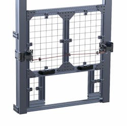
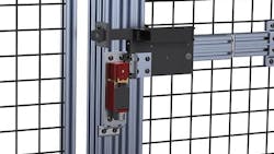
Perimeter safeguarding is perhaps the simplest, most affordable way to create a safer workplace for your employees. No matter the industry, installing perimeter safeguarding around hazardous areas—such as robotic cells, processing lines, press brakes, shears, welders, and other heavy machinery—can significantly reduce the risk of injury by preventing employees from encountering dangerous moving equipment.
In addition, perimeter safeguarding can prevent damage to the machine asset itself, for instance, by warding off malicious tampering or an accidental collision with a passing forklift. Perimeter safeguarding also effectively eliminates the threat of flying debris ejected from the machinery inside striking employees on the outside. Plus, the wire mesh lets those on the outside safely maintain visibility of operations within.
We should note that perimeter guards are also known as “fixed distance guards.” These are not to be confused with awareness barriers, such as railing systems, which do not prevent entry into a hazard zone.
Primary Safeguarding
Before we discuss the details of perimeter safeguarding, let's briefly review the choices available to protect employees working in or around machinery.
- Barrier guards are physical barriers that prevent access to a hazard, whether the danger is a machine, a process or an area. Basically, barrier guards are installed on the machine while perimeter safeguarding is for surrounding a work zone that contains the machine.
- Presence-sensing devices detect the presence of a person or thing and will stop the hazardous motion of the connected machine. This technology includes light curtains, single or multiple-beam devices, area scanners, and pressure-sensitive mats.
- Hostage controls require that a control device, like a two-hand control, be held and actuated therefore enabling a machine to run. A hostage control is fixed in position to keep the operator at an appropriate distance from the hazard. However, hostage controls only protect the individuals using them, so additional safeguarding measures must be taken for other people exposed to the hazard.
Supplemental safeguarding should be considered with the use of awareness barriers, restraints (hold-back devices), awareness signals (audible or visual), warning signs, and color coding throughout the plant floor. Safety procedures, employee training, and personal protective equipment also play important roles in safeguarding employees.
Applying Perimeter Safeguarding
Now that you know the major pieces of the machine-safeguarding puzzle, how and where do you apply perimeter barriers?
First off, a risk assessment and hazard analysis should be performed of the proposed work zone and its contained machinery. This identifies the hazards in the zone and quantifies every risk that employees will be exposed to while operating the machine or maintaining it. Lastly, it presents a tangible, practical action plan based on the findings. Recommendations will factor in what tolerable risk remains when running production, setting up, and maintaining the machines after the barrier's installation.
Before the first barrier is installed, however, you will need to familiarize yourself with the safety standards in North America typically referenced when applying perimeter safeguarding:
- ANSI/RIA R15.06-1999, American National Standard for Industrial Robots and Robot Systems—Safety Requirements.
- CSAZ434-03, Industrial Robots and Robot Systems—General Safety Requirements.
- ANSI B11.19 Performance Criteria for Risk Reduction Measures: Safeguarding and Other Means of Reducing Risk.
These standards require that perimeter safeguards be designed, constructed, attached, and maintained so that personnel cannot reach over, under, around or through the guard or device undetected and reach the hazard. They must be constructed with rugged materials—such as steel or aluminum—that will hold up to an industrial environment and the application. Any fixed portion must require tools to be adjusted or removed.
It's not unusual for openings to be needed in a perimeter guarding system. Those openings must comply with the guard-opening table found in the ANSI and CSA standards. A guard-opening scale can be used to check openings for compliance. Minimum distances from a hazard related to the barrier opening size are as follows:
Differences in Standards
The requirements for barrier guards are largely the same in both the ANSI/RIA and CSA standards. The only difference is in the minimum height requirements of the bottom and top of the guard above adjacent walking surfaces.
- ANSI/RIA R15.06 requires that the bottom of the guard is no more than 12 inches above adjacent walking surfaces and that the top of the guard be no lower than 60 inches above adjacent walking surfaces unless additional safeguarding devices are installed to prevent or detect access to the hazard.
- ANSI B11.19 8.8.7: The opening between the walking/working surface and the lower edge of the perimeter guard shall be no greater than 180 mm (7.09”). Other heights greater than 180 mm (7.09”) shall be permitted as determined by a risk assessment.
- CSA Z434 has the same language except the dimensions are 6 inches for the bottom of the guard and 72 inches for the top of the guard above adjacent walking surfaces.
Interlocked Sections
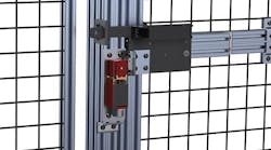
An interlocking mechanism on a perimeter guard stops a machine's operation whenever it is open. Until it is closed, the machine cannot start its operation.
Perimeter guards are mechanical solutions that prevent access to single or multiple hazards. Perimeter guards may be a combination of fixed (non-interlocked) or movable (interlocked or otherwise secured) guards.
According to the standards, when perimeter guards have interlocked sections, each of those sections must provide two sets of contacts unless the risk assessment determines that only one set of contacts is acceptable. In the event that magnetic switches are used, a magnetically coded design is required to reduce the possibility of defeat or interference.
General Requirements for Interlocked Devices
Interlock device design:
- ANSI B11.19 10.2.1.1.1 Interlock devices used to reduce risk to individuals shall be specifically designed and constructed for use in risk reduction applications and comply with all applicable requirements of clause 9 and subclause 10.1.
- 10.2.1.1.2 Components, subassemblies or modules of the interlocking device and its interface or machine control system shall conform to the requirements of 9.2, or shall be designed and constructed to meet the level of safety performance (risk reduction) as determined by a risk assessment.
Switches designed with a positive opening operation should be mounted in a positive mode so that when the actuator is disengaged, the motion forces a non-resilient linkage to open the closed contact(s) tied into the safety-stop circuit. However, if you are using any switch that isn't positive opening, you'll need to set it up so that it is monitored automatically to detect dangerous faults.
A few other caveats: While the interlock must be tamper-resistant and unable to be defeated without tools, it also must be easily unlocked from the inside, with or without power. Finally, to ensure that an employee is out of the hazard area so that automatic operation cannot be accidentally restarted by someone else, your interlocking system should require a key, password, or security code that must be entered before permitting the operator to restart.
Brian Boes is the VP of Applications Engineering & Services at Rockfrod Systems, LLC. Brian is a member of the ANSI B11 Standards Development Committee representing Rockford Systems as a voting member. He's also active on the ANSI B11.1 & B11.2 subcommittees, where he assists in writing the mechanical and hydraulic punch press standards.


