Forging Undercuts in Steel Pistons
European forgers produced 6 billion tons of forgings in 2012, which equals about 22.5% of the world’s forging production[Eur12]. In forging, material and energy costs are among the primary elements of total production costs—with material costs totaling up to 50% for parts made of steel[Rit09].
Besides the cost of forging the part, the subsequent machining process is also responsible for a major part of the final production costs. This is true as well for pistons used in combustion engines, which are high-performance parts with high requirements for mechanical and thermal properties.
Especially in the current market, where performance and efficiency are set by the auto industry’s performance standards, there's a need for new and innovative approaches to meet these requirements.
Producing Pistons
Currently, pistons for cars are usually aluminum castings. But, in general, parts that must withstand high mechanical loads like crankshafts or con-rods for internal-combustion engines usually are forged. Pistons made of aluminum are also forged to increase the mechanical properties of the part, but they're more expensive.
In recent years some research has been conducted on forging and the use of steel pistons[Emm11].
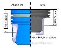
The main advantage of steel pistons is that they can be produced in smaller dimensions than pistons made of aluminum, while keeping the same or even improving the mechanical properties (see Figure 1). Therefore, steel pistons allow smaller engine blocks and increase efficiency due to higher possible compressions and less friction.
Today, steel pistons are used in trucks, but in the near future, it's more likely they will spread to the commercial automotive industry.
After the forging process, the pistons are machined. Functional surfaces, a cooling channel, and holes are established. During machining, larger areas of the pistons, especially near the pin bores, are cut by chip removal.
The volume in this area is about 10% of the total volume of the steel piston. To achieve the pin bores a first clamping has to be done. To be able to perform this clamping operation, the parts have to be prepared by a high-precision machining operation that is both time-consuming and expensive.
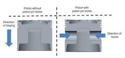
A pre-forging of the areas of the pin bores allows significant material savings and simplifies the first clamping operation. However, these pin bores are located orthogonally to the direction of the forging and represent an undercut (see Figure 2). Such an undercut cannot be produced by a usual (i.e. unidirectional) forging process.
Objectives of the Project
To address these challenges a research project was initiated at IPH – Institut für Integrierte Produktion Hannover, to determine the feasibility of a multidirectional forging operation to produce the pin bores as undercuts. In the course of the research project, the multidirectional forging will be analyzed, first using modern Finite Element Analyzes (FEA) software, Forge NxT.
FEA software is widely used in the forging industry and provides an easy and reliable way to predict forging process results. IPH is an expert in the field of FEA simulations and offers its competence to the forging industry, e.g. for optimization of forging processes.
After a suitable forging sequence—without folds or other defects—has been identified, different parameters that have an influence on the forging sequence will be investigated. Examples of these parameters are the temperature of the billet, the speed of the forging press, or the geometry of the punches used to forge the undercut.
Once an optimized parameter set has been found, the information gained will be used to construct and produce the corresponding forging tools. Then, these tools will be mounted on an industrial-scale eccentric press and tested in an industrial environment. The project plan calls for forging a trial batch of 500 parts.
Once the forging trials are finished, the dies, as well as the parts, will be analyzed.
Die wear is an important factor and the dies will be analyzed to evaluate abrasive die wear as well as wear on the moving elements. The overall quality and especially the feasibility of the first clamping operation directly after the forging process will be assessed. Additionally, the grain flow and mechanical properties will be determined.
Also, a guideline will be written based on the experience gained in the forging trials. This guideline will enable forging companies to use the forging of undercuts for different forging parts, such as suspension arms or hinges that have similar bores located orthogonally to the forging direction.
Finally, the economic feasibility of the process will be determined and the new process evaluated by a comparison to the current forging process.
Multidirectional Forging
In a standard forging process, the ram of the forming press moves downward vertically, and the upper dies make contact with the billet and form it until the desired (pre-) form is achieved. But, the pin bores are located orthogonally to the press movement, so the forming direction has to be changed by 90 degrees to a horizontal direction.
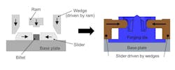
Such a redirection of the press movement can be done by the use of multidirectional forging tools. The basic functionality is shown in Figure 3. Such tools have been developed for flashless and the flash-reduced forging of steering links, con-rods, and crankshafts[Lan15, Beh10].
In a multidirectional forging operation, the vertical movement of the press is redirected into a horizontal movement using wedge drives. Outer wedges are driven by the press ram. As the ram moves downward, the wedges make contact with sliders that move on a base plate. By such a system the change of the movement of the press is possible. Hence, it is basically possible to use this method to forge undercuts.
However, in such a process the upper and lower dies have to be kept closed while the sliders form the part. Therefore, the movements of the upper and lower die and the press have to be decoupled, which is one of the challenges of such a process.
Developing the Forging Sequence, Tools
Forge NxT 1.0 simulation software is used to develop the forging sequence. Based on CAD data of the forged part, preforms and the initial billet dimension were derived first.
Afterward, the sequence simulations of the preforms were performed and analyzed. Adjustments and optimizations were made iteratively, based on the results of the previous simulations to avoid folds or areas where a missing filling of the cavity occurred.
Typical forging parameters for a hot forging process were assumed in the simulations. The initial temperature of the billet was set to 1,200°C (2,192°F), the temperature of the dies was set to 150°C (302°F), and a water-graphite lubricant (µ=0.3) was used.
The pistons are formed in 42CrMo4 (AISI 4137), so the corresponding flow curves are used in the simulations. The initial dimensions of the cylindrical billet were 60 millimeters in diameter and 50 millimeters high.
The first forging operations are similar to a standard forging process but special attention was necessary for the development of the forging of the undercut.
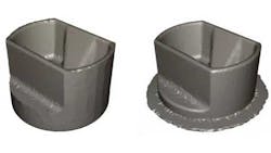
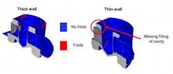
For example, determining the thickness of the piston walls was an important detail to ascertain (see Figure 4).
As shown in Figure 4, different wall thicknesses lead to different issues. On the left side, the thickness of the wall initially was big, with a width of 20 millimeters. This results in too much material in the upper areas of the part, which leads to folds. A part with folds will have to be disposed of as scrap.
On the other hand, a thin wall thickness of a width of 5 millimeters leads also to folds. Additionally, there is a missing filling of the cavity present, which has to be avoided, too. The final solution was to chamfer the thickness of the wall from top to bottom in the final forging, with the thick part at the bottom. Such a chamfered wall is suitable for forging the undercuts without folds or a missing filling of the cavity.
Figure 5 shows a forging process sequence that consists of four stages.
First, the billet is upset. Later, the outer diameter is used to center the billet in the die of the preform. In the preform, the areas of the walls of the piston and the area of the combustion chamber bowl are preformed. In the final forging, the part is finished except in the areas of the pin bores. Last, the multidirectional forging process is used to forge the undercut in the areas of the pin bores.
The final forging step is the one with the highest loads and a maximum press force of about 4,000 kN. About 500 kN is required for each slider to pre-forge the pin bores. Compared to the conventional process that is the current standard for the industry, the material consumption in this process could be reduced by about 7%. The flash ratio is about 6%.
Based on the forging sequence developed the forging tools are being manufactured now. As the multidirectional forging tool is the most complex one, it was developed first.
Currently, there are two possible variants under consideration to keep the dies closed. The first possibility would use disk springs that can be compressed, and the second would use a new closing mechanism based on a guide bar. After the construction of the tools, they will be manufactured and tested on an industrial press.
Summary
Pistons for combustion engines usually are made of cast aluminum. But, increasing requirements for efficiency and performance can be met by steel pistons, and this option will probably gain popularity in the automotive industry in the coming years. The pistons are forged and an expansive machining process is necessary to finish them.
In a usual, unidirectional forging process it is not possible to pre-forge important areas, such as the pin bores as they represent an undercut. With the help of a multidirectional forging operation, it's possible to forge undercuts. FEA simulations already have shown the feasibility of such a process, which is distinguished by a pre-forging of the pin bores and improved material usage.
Furthermore, the following machining operation will be easier due to the simpler positioning of the part.
Currently, the forging tools are under development. Once they are finished they will be tested in an industrial environment on an eccentric press. The tools and parts will be analyzed concerning the quality of the parts, the die wear, and the economic efficiency of this new process.
This research project (IGF project No. 18162N) of the research association for steel application FOSTA is funded by the AiF in the framework program of the industrial research community (IGF) by a resolution of the federal ministry of economic affairs and energy of the German parliament.
The authors are affiliated with the Institut für Integrierte Produktion Hannover GmbH in Hanover, Germany. Dipl.-Ing. J. Langner is the Project Engineer. Dr.-Ing. M. Stonis is the Division Manager, Process Technology. Prof. Dr.-Ing. B.-A. Behrens is a member of the management board, IPH.
Visit www.iph-hannover.de for more information
REFERENCES
