By: Andreas Horat, CTO-AMZ electric, ETH Formula Student Project
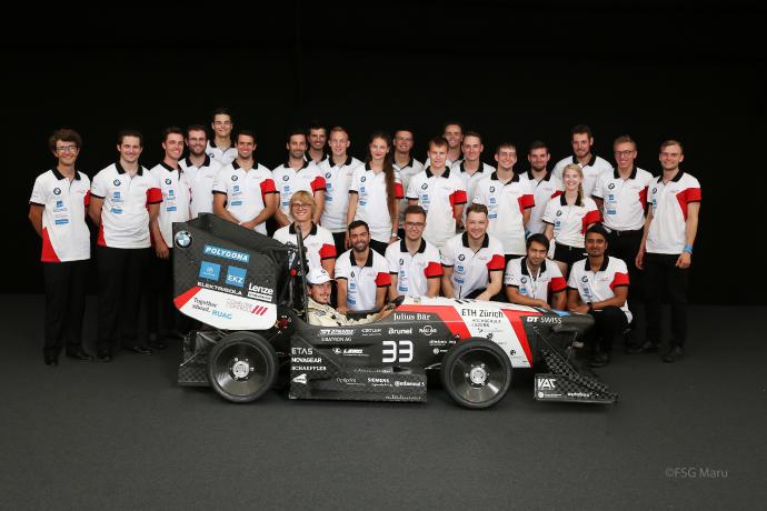
Formula Student - the largest engineering competition in the world (see box) - has 18 events a year, with more than 600 student teams participating. In the twelve-year history, the AMZ (Akademischer Motorsportverein Zürich) racing team, consisting of students from the ETH Zürich and the university of applied science Lucerne, has managed to put itself at the top of the world rankings thanks to continuous improvement of concepts and the introduction of new innovations, like the use of an FPGA module for controlling the electric drive motors. The tenth anniversary two years ago was crowned with the successful world record for the fastest acceleration for an electric car from 0 to 100 km/h in 1,513 seconds. In order to remain competitive, the individual vehicle components must be coordinated and integrated into one reliable and performant system. With most of the components developed and built custom themselves, AMZ can do just that.
The way to the top
The aim of the 2018 vehicle “eiger” – all cars are named after Swiss mountains - was to reach the maximum possible number of points in the competition. This is achieved by driving the fastest lap. By lap time simulation, energy calculations and analysis of the log data of past seasons it was decided to follow a concept with a fully custom four-wheel drivetrain, a Carbon fiber reinforced polymer (CFRP) monocoque, computational fluid dynamics (CFD) and wind tunnel validated aero package and hydraulic suspension.
FPGA module based inverter
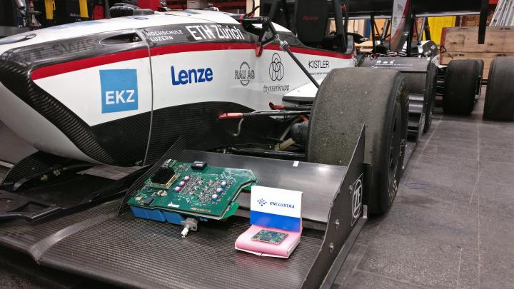
For the first time in AMZ history, the team developed all components of the drivetrain completely in-house. The last missing part was the Inverter. In 2017 the team started the development of a completely custom inverter, based on an FPGA module from Enclustra. The inverter converts the DC voltage from the Lithium battery into the three-phase current to run the permanent magnet synchronous motors.
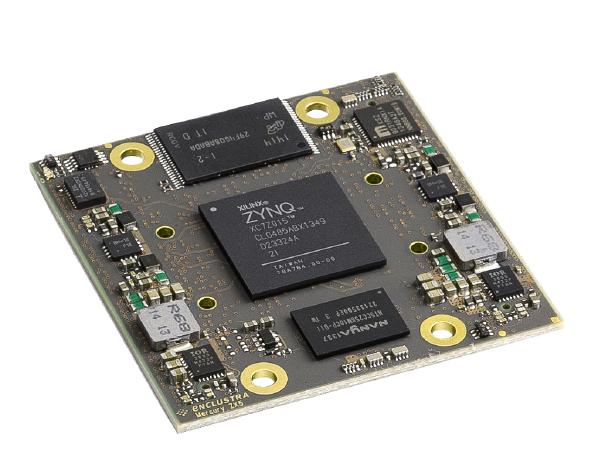
Four self-developed inverters control one motor each. A self-developed direct torque control (DTC) modulator is running on a Xilinx Zynq 7015 FPGA-System-on-Chip based Enclustra Mercury ZX5 module. VHDL implementation makes it possible to estimate the current state of the motor and calculate the new switching positions every 10 nanoseconds – not possible with a microcontroller or DSP based system.
Custom 1200 Volt SiC MOSFET modules with an on-resistance of only 10 milliohms with self-developed intelligent gate-drivers, water-cooled through a 3D printed cooling plate, reduce conduction and switching losses with increased switching speed down to 39 ns rise time. Additional two 47 nanofarad DC-link capacitors on the module decrease power loop inductance. A hybrid dc-link with 6 microfarad Ceralink ceramic capacitors and 240 microfarad film capacitors are used to reduce mass and lower dc-link voltage ripple. Two PCBs are designed with 1-millimeter copper inlets for tractive system connections to minimize board area. To control the motor, the three-phase currents, the dc-link voltage, and current as well as two-phase to phase voltages are measured with up to 1 million samples per second. To determine the current position of the motor a resolver is used. Gigabit Ethernet and CAN connectivity ensure fast and safe communication in the car and on the test bench. The entire inverter software is developed in-house to ensure the highest customizability.
The Enclustra Mercury ZX5 SoC module
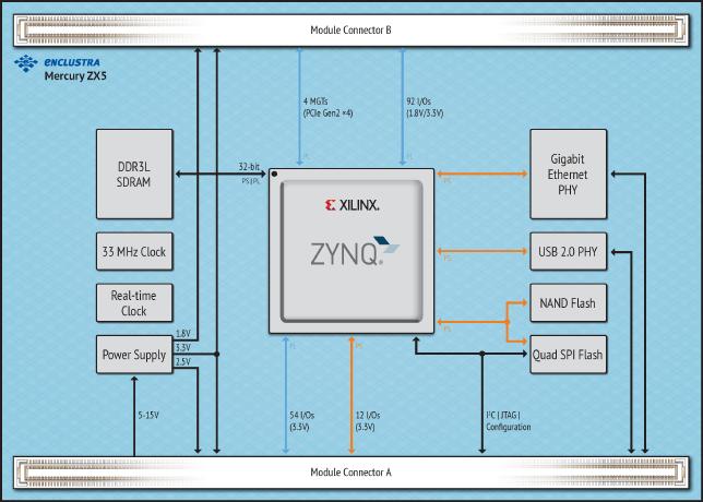
For the processing unit, a system on chip (SoC) was chosen. Bare SoCs are in most cases packaged in a ball grid array (BGA), that is difficult to solder and require a PCB with many layers to route the signals to the chip. The SoC requires also a lot of peripheries such as memory, clock, interfaces and a sophisticated power supply. The Mercury ZX5 SoC module from Enclustra provides exactly all that functionality on one single small PCB. The module contains 1 gigabyte of DDR3L SDRAM, 512 megabytes of NAND Flash, an Ethernet PHY and a power supply for all required voltages. The module even can power circuits on the baseboard, minimizing the need for power converters.
Abundant computing power
The modulator and all the communication to the peripherals are implemented on the FPGA as it requires very low latency and a high update rate. All safety critical functions are implemented on the FPGA, reaching a delay time of at most 1 microsecond for the overcurrent protection and 2 microseconds for the over-voltage protection. A multilayer redundant safety system is implemented on the FPGA and the processor so that the processors and the FPGA monitor each other and shut down the inverter in case of any inconsistencies.
The higher-level controls such as velocity control and traction control are implemented on one core of the ARM Cortex-A9 processor. The second core is responsible for the communication with the vehicle control unit (VCU) or the controlling computer and for the data logging.
High bandwidth interfaces
The compiled firmware together with the bitstream for the FPGA is copied onto an SD card, that gets plugged into the inverter baseboard. At startup, the bootloader then copies the firmware into the memory and loads the bitstream into the FPGA fabric.
The FPGA processes all current measurements with 1 million samples per second (MSPs), while the voltage measurements are processed with 500 kSps. These components are accessed through an SPI-based protocol. The motor position is measured through a resolver with a 33 kSps parallel interface. Besides being used directly by the modulator, the data is transferred to the processor through the integrated AXI PL-PS interconnect. With this technology, the processor can simply change the configuration data and read the values of the FPGA with memory access instructions.
In addition, it is possible to access the DDR3 RAM of the Enclustra Mercury ZX5 module directly from the FPGA fabric. Like this, it is possible to transfer a large amount of log data to the RAM without processor usage. This data is then stored to the SD card for offline analysis before the inverter is turned off.
The temperatures of the semiconductors and the output filter are measured with the built-in XADC of the SoC and directly used on the processor. In the car, the inverter is connected to the VCU via the CAN interface directly to the processing system. To run the inverter on the test bench and to connect it to a computer, the ethernet interface is used.
Simplified power supply
The Enclustra Mercury ZX5 can be powered from a single power supply with a voltage between 5 and 15 volts. It contains the DC/DC converters for all the internally required voltages. The on the module generated voltages are also routed to module connector pins. O the inverter baseboard these 3.3 volt and 1.8-volt rails are used to power the analog and digital circuits. Due to this, the effort for the external power supply is minimized.
Broad design-in support
To ease the integration of their modules, Enclustra provides all required hardware, software, and support materials. Detailed documentation and reference designs make it easy to get started, in addition to the user manual, user schematics, a 3D-model, schematic symbol, PCB footprints and differential I/O length tables are available. Thanks to this the risk of wrong pin alignment is minimized. All arising questions during the development could be solved quickly with the help of Enclustras support.
The next evolution
The new inverter for the 2019 race car “mythen” is again built around the Enclustra Mercury ZX5 module. The even smaller Mars ZX2 from Enclustra has also been evaluated, but this module was not able to fulfill the required number of I/O-Pins. With the new inverter, a fiber-optic link between two Enclustra Mercury ZX5 modules is implemented in the car. For this, the Multi-Gigabit-Transceivers are used.
For “mythen” the drivetrain concept was changed from four inverters - one for each motor/wheel - to a two inverters concept. One inverter with one Enclustra Mercury ZX5 module is controlling two motors now. Thanks to this new concept a lot of auxiliary circuits could be merged, the complexity reduced and also some valuable space saved. In addition, it opens the possibility to implement more advanced control algorithms, which act on multiple motors.
The Formula Student competition
Formula Student is the world's biggest competition for engineers, founded in 1981. The idea of the competition is to introduce future engineers for one year to the development, production, assembly, testing and competition of an electric or combustion race car. More than 600 teams from universities all over the world competing with their self-constructed race cars. The winner is not necessarily the team with the fastest car, but the one with the best package regarding construction, performance, financial planning, and sales arguments.
A separate class for electric vehicles was introduced in 2010 in order to prepare prospective young engineers for future technologies such as electric drivetrains and in order to advance the innovation process.

