MODEL 4813H GPIB TO DIGITAL INTERFACE BOARD
Jan. 31, 2007
Related To:
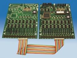
Today, ICS Electronics announced a new GPIB-to-Parallel Interface for interfacing devices with TTL, CMOS or other digital signals to the GPIB bus. Designated the Model 4813H, this two board set expands the number of digital I/O lines available in OEM boards up to 256 lines. Typical applications for the 4813H are interfacing test chassis or relay matrices that need a large number of digital signals to the GPIB bus. The Model 4813H is an IEEE 488.2/GPIB to Parallel Interface that provides 256 parallel I/O lines that can be configured as inputs or outputs in 8-bit bytes. The I/O lines can be controlled as individual bits, or data can be transferred directly to or from a specific byte, or by strings of data characters to multiple bytes. A transparent mode lets the 4813H output high-speed binary data to multiple bytes. The 4813H provides the parallel device with an IEEE-488.2 compatible interface that responds to all of the IEEE-488.2 Common Commands and includes an expanded 488.2 Status Reporting Structure that monitors up to 15 inputs for signal changes. The 4813H also responds to SCPI commands which let the user set its GPIB address, configure the parallel interface to match the application and enter a custom IDN message. All configuration parameters are saved in nonvolatile Flash memory. The 4813H is a two-board set with a Master Board and Expansion Board interconnected by a short flat-ribbon cable. The Master Board contains ICS's standard diagnostic LEDs for troubleshooting GPIB problems, a reset button, a GPIB header and a 150-pin connector with the first 128 digital I/O signals. The Expansion Board has a similar 150-pin connector with the second 128 digital I/O signals. Both boards are 7.0 in x 5.5 in boards that can be mounted against a panel or on a PC board. When mounted on another PC board, the mated height is less than 0.5 inches. The 4813H two board set uses less than 900 mA of regulated 5 Vdc power. Connection to the GPIB bus is via one of ICS's GPIB Connector/Address Switch assemblies that mounts the GPIB Connector and an Address rocker Switch on the rear panel of the host chassis. Size, L x W x H 7.0 x 5.5 x 0.55 inches (178 x 140 x 9 mm) Connector and Headers GPIB/Addr: 26-pin 3M 2526 male connector Digital I/O: 150-pin, 3 row male Conn. Temperature Operation -10° C to +70° C Storage -20° C to +85° C Humidity 0-90% RH without condensation Power +5 Vdc @ 440 mA (typical) 880 mA for Expansion Board Kit


