Here’s How To Know if Your LED Lights Are Compliant
Download this article in PDF format.
Manufacturers and users of LED lighting applications need to be assured that their products will be qualified according to a multitude of reliability and efficiency standards.
In addition to voluntary initiatives and programs like EnergyStar, mandatory standards and specifications for the lighting industry must be kept in mind during project development, including the latest IES LM-79-19 and the ANSI C82.16 documents.
This article gives an overview of relevant lighting standards and specifications for LED lighting products. It also describes the features of Vitrek’s test equipment, including the PA900 power analyzer—featuring built-in lighting specifications—as well as Vitrek’s electronic DC loads and hipot testers.
These portable testing devices, with their selectable touchscreens and other user-friendly features, allow engineers and technicians to easily confirm that their LED lighting products meet the necessary parameters for performance, energy efficiency, verification, and safety—before the products are sent to testing facilities.
Industry Standards for LED Lighting
Over 40 years ago, during the U.S. oil crisis, the Department of Energy (DOE) established the Energy Policy and Conservation Act to compel manufacturers to develop products meeting certain efficiency specifications in order to save energy, including those for solid-state lighting (SSL) products.
The focus of this white paper is on the mandatory standards/specifications for the LED lighting industry. The following sections discuss the IES and ANSI mandatory standards, as well as the voluntary initiatives and programs that lead to certification and the product labeling (e.g. EnergyStar) that indicates compliance.
The IES LM-79-19 Standard and Specification for SSL Lighting
Updated in 2019 for the first time since 2008, the Illuminating Engineering Society’s (IES) LM-79-19 is the standard and specification for solid-state lighting applications.
In addition to specifying optical measurements (lumens, chromaticity, luminous flux, etc.), the LM-79- 19 has stringent system efficacy specifications. For the LED lighting applications, the relevant parameters fall under “AC Power Supply Standards” (sections 5.1 through 5.3), including:
- Optical measurements (lumens, chromaticity, luminous flux, etc.)
- Electrical Power (voltage, current, power, power factor) with k=2 confidence interval. In the updated 2019 LM79 standard, the specifications for electrical power have been boosted from a K=1 to a k=2 “confidence interval.” This means that when doing calibrations, the measurement equipment must have a K=2 confidence level of being 95% accurate within plus or minus two standard deviations of the mean.
- AC Voltage (60 Hz): 0.4% or less
- RMS Current: (0.5Hz to 1kHZ ) 0.6% or less / (1kHz to 100kHz) 2.0% or less
- AC Power: (0.5Hz to 1kHz) 1.0% or less / (1kHz to 100kHz) 2.0% or less
- DC Voltage: 0.1% or less
- DC Current: 0.1% or less
- Power Factor: PF>=0.7
- System Efficiency (Lumens/Watt (Lm/W), Driver Efficiency, if not integrated)
- Physical and environmental (temp, vibration, airflow, etc.)
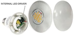
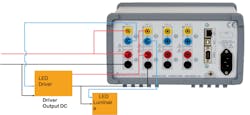
As shown in Figure 1, the LED driver can be integrated into the LED lighting fixture itself. In this case, the input power coming into the luminaire’s LED driver (power supply), as well as its output power, must be measured using test equipment to compute system efficiency (Figure 1).
The ANSI C82.16-15 Standard & Specification for LED Drivers
Updated in 2015, the American National Standards Institute’s (ANSI) C82.15-15 is a mandatory standard and specification for the methods and measurement of LED driver input and output parameters.
This includes:
- LED driver electrical input parameters: Voltage (open-circuit voltage (OCV), peak, ripple), current (peak, ripple), power, power factor (pf), total harmonic distortion (THD), inrush
- LED driver electrical output parameters: Voltage (OCV, peak, ripple), current (peak, ripple), power, energy efficiency
Energy Star & Other Voluntary Energy Initiatives
In addition to mandatory EIS and ANSI standards/specifications, lighting products can be tested to meet voluntary national and state certification programs and initiatives that enable energy savings.
These national and state programs/initiatives have different objectives and requirements, each with precise measurements and unique submission requirements to assure compliance.
The ones that deal with LED lighting applications include:
- Energy Star: EPA/DOE programs - Minimum luminous efficacy (LED power 10 W; 55 Lm/W)
- Design Lights Consortium (DLC): Utility-based programs - SSL technical requirements V5.1 (80 to 120 Lm/W, minimum efficacy), decided by product type (LED lamp, outdoor lighting, etc.)
- California Energy Commission (CEC): Mainly energy efficiency - Standby power 200 mW or less; PF 0.7 or greater
- LED Lighting Facts: DOE program is mandatory for Energy Star
- MSSL (Municipal Solid-State Street Lighting): DOE program focusing on outdoor lighting (streetlights, parking lots, garages, etc.)
When an LED lighting product completes qualification for one of these programs/initiatives, a label appears on the product packaging to show that the specification has been met (e.g. light output per Watt)
International Standards for Compliance Testing
The international Electric Commission (IEC) provides international standards that bring together the agreed-upon set of rules, specifications, and terminology that allows manufacturers to have their devices tested for conformity.
The following specifications are relevant for testing LED lighting systems:
- Power Consumption Testing:
- The EN50564:2011, which replaces the IEC62301 specification, specifies test procedures for low-power consumption equipment and offers guidance for specifying measurement equipment—such as power analyzers—used for such tests.
- It describes how to test products with a supply voltage between 100 and 250V AC.
- It may also apply to 3-phase equipment and may be used in conjunction with other standards for measuring energy efficiency, such as Energy Star and EU standby power directives.
- Harmonics Testing:
- EN61000-3-2 test standard specifies limits of harmonic components of the input current which may be produced by equipment tested under specified conditions. (Class C of the specification is for lighting devices.)
- IEC61000-3-12 deals with the limitation of harmonic currents injected into a system, such as a lighting system or electrical ballast.
- IEC61000-4-7 is applicable to instrumentation intended for measuring spectral components in the frequency range up to 9 kHz which are superimposed on the fundamental of the power supply systems at 50 and 60 Hz.
Vitrek Testing Equipment for LED Lighting Products
As is apparent from the previous sections, there are four areas of parameters covered by industry standards as listed below, for LED lighting products. Therefore, to assure they will eventually pass UL, TUV, Intertek, and SA testing, engineers and technicians should analyze these parameters during each phase of product development.
- Performance Parameters (design phase)
- Photometry (lighting measurements) lumens, chromaticity, luminous flux
- Electrical (voltage, current, power)
- Energy Efficiency Parameters (design/production phase)
- Luminous efficacy (the amount of electrical input power vs. the amount of light power coming out on the other end of the fixture.
- Energy efficiency of LED drivers
- Verification Parameters (production phase)
- Consumption (e.g. hooking up LED lighting device to a power analyzer to monitor power over a certain period of time.)
- Safety Certification Parameters (final test phase)
- Shock hazards, fire, and health concerns
Vitrek’s test equipment has years of proven effectiveness for the lighting industry. The devices described in the following sections are used to test LED lighting applications by measuring the performance, energy efficiency, verification, and safety parameters needed for compliance testing and certification.
Vitrek PA9xx Power Analyzers
Vitrek’s PA9xx series of power analyzers measure performance, energy efficiency, and verification parameters of LED lighting products during the design, production, and verification phases of the device’s development.
The compact, small-footprint, lightweight PA9xx device is easy to handle and meets the updated LM-79-19 specifications for the higher K-2 accuracy requirements.
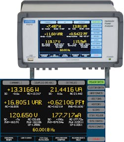
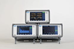
The power analyzer’s power data screen (Figure 2) makes it easy for the user to check to see if LED applications meet all required specifications by showing the following parameters: voltage, current (ripple), power, apparent power (VA), reactive power (VAR), power factor (PF), frequency, and efficiency.
LED Driver Efficiency
The Vitrek power analyzers work as virtual power analyzers (VPA) by connecting one to four channels, as needed. By providing the ability to integrate separate power analyzers into the same instrument, the device essentially makes each channel into an individual PA channel.
In the following example (Figure 3), the PA is hooked up to an LED luminaire to test LED driver efficiency, making sure the product meets specifications for compliance. The back panel of the power analyzer in Figure 3 shows two of the channels.
On the LED driver side, the input to the LED driver is a 120V AC input signal and the output is a DC signal (typically around 10V.)
As shown, the 120V input power (the red and black wires) is routed and connected as channel 1 for voltage. On the current side, the input current is routed into the power meter and back out (blue) to the input side of the LED driver. So the voltage and current are on channel 1.
The output of the LED driver—the red/black connections for voltage—is connected to channel 2. For testing, the LED driver output current is run to channel 2 of the power analyzer and then back out. It's then connected to the LED luminaire.
With the power analyzer and LED driver hooked up to two channels, the PA’s touchscreen panels are used to measure and display the LED driver’s efficiency.
As shown in Figure 4, the input to the LED driver (the top, upper-right side of the panel) is assigned as input number 1 (purple square: “Config VPA, VPA1.”) This depicts the input to the LED driver to show efficiency, as shown as “EFF/LOSS” in the purple square on the right.
As illustrated by the screen in Figure 5 (above), the LED driver’s output is assigned as channel 2, displayed as “CONFIG VPA 2” on the top-right (purple square)
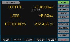
Configuring the device to show different parameters is done by using the touchscreen to toggle between display screens. In this way, the PA9xx makes it simple to calculate the output/input power of the LED driver by showing output, loss, and driver efficiency, as shown in yellow in Figure 6.
Compliance Testing - Standby Power
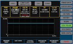
To simplify LED lighting compliance testing, the Vitrek PA9xx family of power analyzers has the portion of Energy Star’s EN50564:2011 5.3.2a specification for standby power built into the unit (Figure 7, in the purple “configure” button at the top of the display).
In this example, the analyzer is hooked up to a smart LED lighting fixture. The user can touch the standby power button (right side, in green,) hit the power button (bottom, red), and push start to see standby power in volts, etc.—displayed on the screen.
When measuring standby power in a smart lighting application, the fixture itself can be turned off while its electronics are being constantly monitored to communicate over the internet or to an app. The PA9xx is useful for measuring standby power in this case as well.
Compliance Testing - Harmonics Emissions
Similar to the standby power feature, the PA9xx family of power analyzers also has the AEN61000-3-2 and 4-7 specifications for harmonics built into the units. It allows the user to select which classification of EN61000 3-2 is displayed (Figure 8).
As shown in Figure 9 (above), the red “tick” marks on the harmonics screens indicate that the LED lighting device is failing the harmonics testing for the required Class A harmonics levels.
The harmonics screen on the PA920, PA910 or PA900 power analyzer displays up to 500 harmonics at a time, even at aviation frequencies.
Additional features include:
- Dual display, both graphical and numerical
- Individual channel
- Voltage, current or power harmonics
- EN61000-3-2 and 3-12 (50th harmonic)
- User harmonics levels (limits)
- Linear or logarithmic display of values or %
- Frequency, THDf, THD sig
It also provides scope mode and cycle mode screens to display ripple and cycles when calculating LED lighting measurements as seen in Figures 10a and 10b.
Scope (Ripple) View:
- Up to six traces can be displayed at a time
- Each trace has user-selectable:
- Scaling, offset, and color
- Time base, trigger, and trigger position
- Accuracy as high as 0.03%
Cycle View:
- Single-cycle view of up to four parameters with unlimited zoom capabilities.
Electronic DC Load
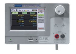
Vitrek’s DL Series Electronic DC Load is used to check performance and energy efficiency parameters for LED lighting during the project’s design and production phases of development.
LED drivers, the power supplies for LED lighting applications, need to maintain a constant current even if the load increases.
Compact and portable, Vitrek’s programmable DC load (Figure 11) can be used where the LED application is installed to detect if the current is stable and luminous intensity (luminous flux) stays within reason even if the load changes.
The DL series electronic DC load is available in six different models with three different voltage and wattage levels.
V7x and 95x Series Hipot & Ground Bond Testers
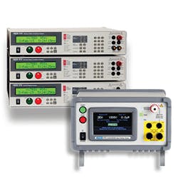
Vitrek’s hipot testers (V7x series and 95x series) can be used during the final production testing phase to make sure an LED lighting product will pass safety certification testing.
The different hipot tester models perform various tests according to each series including AC hipot, DC hipot, insulation resistance, continuity, and ground bond.
The V7x series can test 5KV AC/DC directly from the front panel. The 95x series hipot tester offers increased accuracy, speed, and drive current. External options are offered with up to 30KV testing on the AC side and up to 15KV on the DC side.
Vitrek 964i High Voltage Switching System
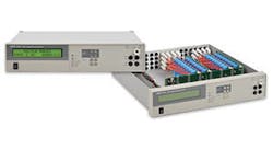
Vitrek’s 964 high-voltage switching system (Figure 13), can be used with the Vitrek V7x and 95x series hipot testers during the final test phase of product production.
For example, on a production line making LED drivers, 10 Vitrek hipot testers can test up to 10 LED drivers at the same time. Alternately, one Vitrek hipot tester can be used with a 964i high-voltage switching system to test all 10 LED drivers. In this case, the switch will introduce the voltage from the hipot tester into the front panel.
A series of relay boards, shown in Figure 13, will take high voltage and switch it to multiple points, so 10 relays can switch from relay 1 to 10 to test 10 different LED drivers very quickly.
Additionally, when used together, QT Enterprise software can configure the 964i switching system at the same time as the hipot tester, and saves the results for later use if audited or requested by customers.
Conclusion
Manufacturers and engineers are challenged with making sure their LED lighting products meet industry standards to pass UL, CSA, TUV, Intertek, and other specifications.
As discussed, Vitrek offers portable, easy-to-use equipment ideally suited for LED lighting testing during each phase of product development.
- Performance (electrical) testing during design: Power Analyzers, Electronic DC Load
- Energy efficiency testing during design/production: Power Analyzers, Electronic DC Load
- Verification (consumption) testing during production: Power Analyzers
- Safety certification during final testing: Hipot testers and high-voltage switching system
Vitrek’s PA9xx power analyzers have built-in LED lighting specifications for standby and harmonics standards, as well as display screens that toggle between a wide range of required parameters. Vitrek also offers the DL series digital DC electronic load, the V7x and 95x series hipot testers, and the 964i high-voltage switch.
Download this article in PDF format.


