4D Additive Software Supports 3D Nesting for Higher Efficiency
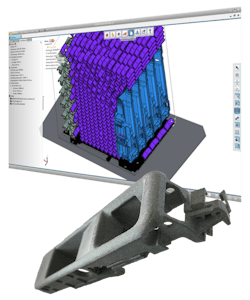
The new version of the universal 3D printing software 4D_Additive 1.6 features an AI-supported nesting technology that increases efficiency when operating selective laser sintering (SLS) and multi-jet fusion (MJF).
CoreTechnologie has enhanced the nesting module of its 4D_Additive 1.6 software for the automatic placement of parts in the virtual build space of a 3D printer.
By intelligently pre-sorting parts that will be nested and improving calculation accuracy, the software now achieves better packing densities, leading to a reduced printing time with the same number of parts thanks to a lower packing height. The increased packing density and lower overall height lead to shorter machine running and cooling times.
To avoid heat pockets and achieve optimum surface quality, nested parts need to be evenly distributed. After the actual nesting, an automatic optimization process takes place and ensures that heat pockets are avoided by slightly rearranging the components in the X, Y, and Z directions. The lowest height achieved during nesting is also maintained during heat optimization.
Calculation speeds of the new nesting function now take less time due to the multiprocessor calculation and optimized memory management.
Large parts are also able to be nested more precisely and will be evenly distributed based on available space. Gaps between the big parts can be efficiently used for the smaller parts. Since the nesting technology creates high packing densities, parameters can be used to limit the maximum packing density and temperature development.
Case Example
Printing with the HP MJF 4200 printer with a build height of 15 in. (380 mm) and 16 hours is nested with a reduced build height of just 11 in. (283 mm) instead of 14 in. (357 mm) thanks to the nesting function.
With the 1.6 Version, the overall height is reduced by 3 in. (74 mm) and the printing time is reduced by 3 hours. The packing density increases from 8% to just over 10% and the duration of the nesting process is reduced from 8 to 3.5 minutes.
With 250 production days per year per machine, an increase in efficiency or reduction in running time of 3 hours results in additional productivity of around 750 hours. The reduced cooling time resulting from the shorter printing time potentially saves up to an additional 9 hours.
4D_Additive Manufacturing Software Suite reads all common CAD formats and prepares for additive manufacturing processes directly as an exact, intelligent, and light B-Rep geometry.
It can read CAD data from 24 different formats such as CATIA, NX, SOLIDWORKS, Creo, Inventor, STEP, and JT as exact B-Rep geometry including all product manufacturing information (PMI), attributes, and design history. It can also process triangulated formats such as stl, obj, and 3mf.
The CAD models optimized for 3D printing and nested on the build plates can be saved in all common formats such as amf, 3mf, and STL as well as in common slicing formats cli, sli, abf, svg, sls, usf, and g-code.
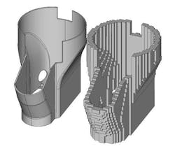
The Texture Module allows users to access more than 5,000 different texture surface structures. 4D_Additives makes it easy to define textures on the CAD model. Simply select the desired surface areas and then apply texture from the database. The size, resolution, position, and height of the structure can be visually adjusted, and a rendered, photo-realistic representation of the model facilitates the work. The software automatically ensures distortion-free projection of the grain over surface boundaries and the precise graphical representation allows real-time assessment of the designed geometry for designing new parts.
The B-Rep kernel offers quality checks, repairs, and preparations of models in accordance with CAD-engineering standards which are based on exact geometry. In conventional 3D printing tools, CAD models are often already triangulated during the reading process and converted into an imprecise STL description. 4D_Additive enables the check, repair, and handling of the exact original B-Rep data according to VDA 4755/2 standard.
These functions analyze the CAD models and automatically eliminate gaps, overlaps, mini-elements, twisted faces, and other errors. Errors that are not automatically correctable are identified and can be corrected within seconds through the clean-up and modeling functions.
For the best possible heat distribution, the software automatically indicates massive zones that are areas with very large wall thicknesses, in which heat concentration possibly takes place. These areas are highlighted in color and provide information for future component design or positioning of the component.
The wall thickness checker can be used to find the areas that are critical for certain processes due to very small wall thicknesses. In addition, the gap measurement detects problem areas and details that are too small for the respective method, such as holes with too small a diameter.
Price: Contact the company for pricing
CT CoreTechnologies Inc.
Southfield, MI
(248) 996-8464
[email protected]
www.coretechnologie.com


