Precision formed parts demand precision inspection to verify dimensional and surface accuracy, and thus to justify the manufacturer’s investment in the forming. The issue of precision becomes even more critical in high-volume manufacturing operations, like forging gears, intensifying the need for advanced inspection capabilities.
Gears are not high technology, of course, but they are conceived as interactive parts, so the degree of precision starts at the design level. High-tech comes into consideration for inspecting gears, however.
Gleason Corporation recently introduced the 300GMSL inspection system, which incorporates multiple gear-inspection methods on a single device platform. Gleason develops and manufacturers a portfolio of manufacturing, handling, and inspection systems for gears and power transmission systems. It supplies operations supplying automotive, commercial truck, aircraft, mining, energy, construction, power tool, and marine manufacturing.
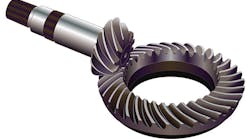
The 300GMSL inspection system provides the classic tactile probing methods for inspecting conventional gear data on spur and helical cylindrical gears, as well as straight, spiral, and hypoid bevel gears with a diameter of up to 300 mm.
More than that, the new inspection system allows non-contact laser sensor scanning of tooth flanks to support gear development. According to the system developer, complete topography data can be recorded more quickly than with conventional tactile probing, and with comparable results.
The option to integrate laser scanning and associated 3D graphics with a CAD interface considerably expands both the functionality and the range of applications for the new machine platform. The new option recommends the 300GMSL for research and development projects, either for prototypes or for parts in production, or when reverse engineering is necessary.
The 300GMSL inspection system is effective in standard production processes, for example, conducting rapid topographic measurement, fulfilling the increasingly stringent requirements of gear inspection.
Other options available via the new system are surface finish measurement and Barkhausen noise analysis, to inspect grind burn, which will be effective at cutting gear production costs, or to perform regular maintenance and certification. The multiple functions available on a single machine platform also reduce space requirements.
Gleason also recently introduced its 300GMSP analytical gear inspection system, designed for use directly in gearmaking production, which presents reliable measured results in demanding surroundings. It does this with integrated systems that compensate for temperature fluctuations and dampen vibration in the manufacturing process. It is well suited for applications in aerospace and automotive manufacturing, but also works in inspection of other high-quality gears.
Inspecting gears is a common task for non-contact 3D metrology systems. For example, Nikon Metrology Inc. offers the HN-C3030 system anchored by a high-speed laser scanner.
The five-axis control capability scans complex parts from optimal scanning angles. It scans complex gears — hypoid gears, bevel gears, helical gears, spur gears, internal gears — quickly, establishing a detailed point cloud that identifies even the smallest imperfections. It can also be used for even more complex parts in high-volume production, like turbocharger wings or oil seals. The results can be used for root-cause analysis.
The high-density acquisition of in-line point clouds with a point pitch of 20 µm enables not only analysis of shapes but also of surface waviness. At 120,000 points per second for data collection, inspection of all tooth surfaces on a single automotive bevel gear can be completed in about five minutes.
According to Nikon, the HN-C3030 provides the lowest ES, MPE of 5 µm of any commercially available non-contact system. Specially developed optics, such as new cylindrical lenses for laser scanner light emitters and an image-side telecentric optical system, achieve high-precision non-contact measurement. The HN-C3030 is able to detect imperfections on glossy or dark surfaces without manual preparations, such as powder spraying.
An important advantage of a non-contact laser scanning system is that it eliminates the need for probe tip radius or deflection compensation. The HN-C3030 can be set up for synchronized, five-axis inspection by integrating it with a high-precision, three-axis (XYZ) drive system (MPEE 1.6 + 4L/1000 µm [L=measured length, mm/JIS B 7440-2:2003]). An angular rotary stage and a rotatable laser scanner swing arm allow laser scanning of wide areas, even the bottom surfaces of parts. Further, the direction of the laser scanner can be changed to allow scans of various shapes from optimal angles.
Possibly the most common approach for inspecting gears is coordinate metrology, as performed by a coordinate measurement machine (CMM.) John Fox, a senior CMM software application engineer for Mitutoyo America Corp., recently wrote that many high-volume operations (including automotive OEMs) have adopted CMM “for gear measurement, production, and setup,” as have high-precision gear manufacturers.
CMMs are less expensive to install than more dedicated, high-tech gear inspection systems, which may cost twice as much as a CMM machine equipped with a rotary table, high-speed scanning probe head, and gear-checking software.
The type of CMM used to measure gears depends on the part’s size and weight. To measure large gears (e.g., diameters of more than a meter) or very heavy parts, a high-precision, horizontal-arm CMM with a rotary table is necessary. But, inspecting large-scale gears is easier with this type of CMM because of its open-access structure. Bridge CMMs are usually the right machine for measuring small or medium-size gears.
In addition to replacing dedicated gear inspection equipment, CMMs can replace many of the smaller, handheld, and functional gages frequently used to inspect gears. “Handheld gages are subject to operator interpretation,” according to Fox. “Repeatability between operators using manual inspection methods is lower. Speed of measurement is certainly slower. Written reporting is open to incorrect values being recorded. An automated CMM can be measuring parts, while the operator continues to produce parts. Once the CMM program is proven out, you know you will get good accuracy, repeatability and reporting.”
It’s even possible for a CMM to be installed on the shop floor, to inspect parts as the gearmaking process proceeds.
“The two major enemies for a CMM are rapid and dramatic temperature changes and vibration,” Fox wrote. “Even when on a shop floor, if the temperature is somewhat stable, there is no major noticeable error.”
