A Closer Look at Transient Voltage Suppression (TVS) Diodes for ESD Protection
Download this white paper in .PDF format by clicking the download button below.
Transient voltage suppression (TVS) diodes help protect electronic circuits from surge voltages associated with an electrostatic discharge (ESD) event and are commonly placed alongside I/O lines, audio hardware, human interface devices, power supplies, and an antenna’s RF front end (RFFE).
TVS diode simulation presents certain challenges. Full-wave time-domain electromagnetic (EM) solvers can analyze a device’s 3D CAD geometry, but the circuit component models are limited. Alternatively, circuit solvers can simulate complex nonlinear elements, but 3D EM effects and signal delay are approximated as inductors, capacitors or distributed elements, such as a transmission line.
A new capability to solve these issues, XFdtd’s transient EM/circuit co-simulation capability, combines the strength of 3D full-wave electromagnetic simulation with the flexibility of circuit solvers. This approach embeds a transient nonlinear circuit solver in the full-wave simulation so that all electromagnetic phenomena are accounted for in a single time-domain simulation.
RFFE Connected to an External Antenna
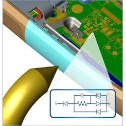
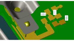
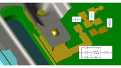
As an example, we'll consider a TVS diode protecting the circuitry of a matching network. Motorola Mobility provided the 3D CAD model, which was then modified for demonstration purposes to include an external antenna that was matched using a simple series capacitor and shunt inductor. The TVS diode protects these components, as well as a 50 ohm resistor acting as the integrated chip (IC) terminal.
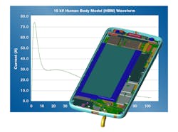
An ESD gun with a current source using a 15 kV human body model (HBM) waveform is applied to the external antenna. The TVS diode is placed in front of the matching network, redirecting the surge current to the ground. The manufacturer provided the current voltage characteristics of this TVS diode as an equivalent SPICE circuit model.
Full-Wave EM Simulation With FDTD
The finite-difference time-domain (FDTD) solution is a full-wave technique based on Maxwell’s equations. 3D CAD geometry is discretized into rectilinear cells and a material property is associated with each cell edge.
At the beginning of the FDTD simulation, all fields are initialized to zero and the current source introduces fields into the simulation space at the tip of the ESD gun based on the 15 kV HBM input waveform. As the simulation progresses, the electromagnetic fields propagate through space and interact with 3D material structures along the way.
Each cell edge has an associated electric field that varies with time. Each cell edge is also surrounded by four magnetic fields, which are used to compute the corresponding current. In this manner, currents both at the source and at the IC terminal are calculated as a function of time. Transient currents are high in this unprotected configuration.
Circuit Simulation
The simulation space for circuit simulators is defined in terms of terminals, elements, and edges. This network is formulated into a nodal matrix equation describing the components, as well as their connectivity information. An iterative solver computes the nonlinear system of equations based primarily on Kirchoff’s Current Law (KCL), which states that the algebraic sum of currents leaving any node must be zero.
In this example, the current source employing a 15 kV HBM waveform is connected to the matching network and IC terminals. The TVS diode is placed before the matching network.
The 3D geometry of the device is unaccounted for in the circuit simulation. If there is prior knowledge of the geometry’s behavior—such as transmission lines and structural inductance and capacitance—additional circuit elements could be added. However, it would be only an estimate of the electromagnetic effects of the structure.
The current at the IC terminal is plotted as a function of time. The lack of time-domain variability indicates an overly simplified representation of the 3D model.
Transient EM/Circuit Co-Simulation
XFdtd’s transient EM/circuit co-simulation uses both computational techniques simultaneously in a single simulation. A cell edge in a full-wave FDTD simulation is linked to the pair of terminals spanning the TVS diode in the circuit solver. The circuit solver simulation space is reduced to only the two terminals, six elements, and numerous edges associated with the TVS diode circuit model.
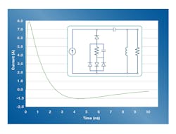
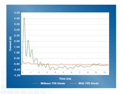
The protection provided by a TVS diode is apparent when comparing the results of a transient EM/circuit co-simulation containing a diode and an FDTD simulation without one. The current at the IC terminal is significantly reduced when the diode is present.
In addition to verifying protection, the ringing in the time-domain voltage confirms that all electromagnetic phenomena are accounted for. The ringing is caused by the inductive and capacitance properties and coupling to nearby structures.
Summary
Effectively simulating TVS diode protection requires a transient nonlinear circuit solver to be embedded in a full-wave electromagnetic solver. This type of simulation simultaneously captures all electromagnetic phenomena from the 3D CAD geometry, as well as the complex nonlinear behavior of the circuit model. ESD engineers can apply this simulation technique in XFdtd in order to analyze device protection measures and mitigate ESD events more effectively.

