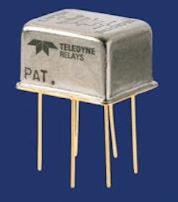
Attenuator Relay Design Improves Performance in Ultraminiature Package
Aug. 9, 2006
Related To: Teledyne Relays
An innovative electromechanical attenuator relay — which incorporates the attenuator circuit and bypass path inside the relay — is finding a growing list of applications because it extends the frequency range of the attenuator while maintaining an ultraminiature package size. Ultraminiature electromechanical relays have been used to switch RF signals for many years. One common RF switching application is to attenuate signals by using a relay to switch the signal to an external attenuator circuit. The external attenuator circuit is generally a resistor network, where the resistor network may be several times larger in size than the relay, particularly at high power. This approach increases the total package size and limits the frequency response of the attenuator. High Performance The new A152 relay from Teledyne Relays has demonstrated numerous advantages in RF switching applications. Reasons include: • High isolation between the signal path and the control voltage. • Low insertion loss of relay contacts. • Insertion loss repeatability of ±0.1 @4.5 GHz • A large bandwidth, allowing usage from DC to 5 GHz. The RF characteristics of the A152 are stable over the temperature range of -55°C to +85°C. Unlike plastic RF relays, the A152 is hermetically sealed and can be exposed to extreme environments. The A152 is currently offered with a 20dB attenuation path. Other attenuation values such as 1, 2, 4, 8 and 16 dB are also available. This high performance comes in a very small package. The A152 attenuator relay measures 12.07 x 9.53 x 7.11 mm (.475 x .375 x .280 inches). Six leads are spaced on two rows 5.08 mm (0.20 inches) apart and spaced 3.81 mm (0.150 inches) on centers. The unit weighs less than 3.12 grams (0.11 ounces). High Reliability The A152 is an extremely reliable attenuator relay as well. Life tests were performed at 125°C while switching 1 watt, 2 GHz CW power. The test was stopped after every 1 million cycles to measure the attenuation. After 10 million cycles, the attenuation changed less than 0.5% in the frequency range from DC to 1 GHz. The change was less than 1.0% in the frequency range from 1 to 2 GHz and less than 3.0% in the 2 to 3 GHz frequency range.


