MULTI-ZONE PID CONTROLLER AND DATA ACQUISITION SOLUTION NOW SUPPORTS RAMP/SOAK CONTROL
Aug. 1, 2008
Related To: Red Lion Controls
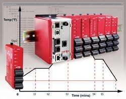
Red Lion Controls, Inc. announces that its Modular Controller series PID modules now support ramp/soak control. The Modular Controller provides multi-zone PID control, data acquisition and I/O for PC, DCS or PLC control systems, while integrating data logging and advanced alarm management. Now, with the latest update to Red Lion’s simple-to-use Crimson® 2.0 programming software, users can integrate multi-segment temperature profiling for complex processes in the autoclave, heat-treating, food and chemical industries. The ramp/soak functionality consists of a profile, or succession of setpoint ramp and soak periods. The profile can support up to 30 segments, with each segment defined by a setpoint and a time, allowing users to set a temperature range and period of time in which the range will be maintained. The Modular Controller’s dedicated single and dual PID modules each manage ramp/soak control individually, maintaining independence for each loop and allowing hot-swappable replacement for reduced downtime. Plus, advanced modes are available for critical control requirements, such as guaranteed soak times and ramp rates. “The Modular Controller delivers advanced PID control as well as an integrated IT-ready data logger and alarm management system for timely notification of critical system data or alerts in unmanned applications,” said Jesse Benefiel, Red Lion product manager. “With the addition of ramp/soak setpoint control, the system can be used for advanced control in any temperature sensitive application.” Benefiel adds, “Plus, simple drag-and-drop data mapping allows the profile recipe to be controlled via any external device or directly by the Modular Controller master for even greater programming flexibility.” The Modular Controller features an advanced, built-in protocol conversion facility and multiple-protocol Ethernet port that allows even the most complex PID, data-acquisition or I/O systems to be configured—simply and in just minutes. Plus, the Modular Controller utilizes Red Lion’s free Crimson 2.0 software for communication configuration and calibration of new systems.• POWER: Derived from system backplane. (CSPID1 draws 150 mAmax. load • on power input of MASTER, CSPID2 draws 125 mAmax). Modules may be • hot-swapped (Replaced while powered up). • LEDs*: • STS - Status LED shows module condition • OP1, OP2, OP3,OP4 - Indicate status of outputs 1, 2, 3, and 4 • ALM, or AL1 and AL2 - Alarm LEDs are lit during any internal alarm • condition • *Default configuration. • MEMORY: Non-volatile memory retains all programmable parameters. • MASTER also stores the parameters in order to reprogram modules that are • replaced. • INPUT: • GENERAL: • Sample Time: 67 msec (15 Hz) • Common Mode Rejection: >110 dB, 50/60 Hz • Normal Mode Rejection: >40 dB, 50/60 Hz • Temperature Coefficient: 0.01%/°C • Step Response Time: 200 msec typ., 250 msec max • TEMPERATURE INDICATION ACCURACY: ± (0.3% of span, +1°C). • Includes NISTconformity, cold junction effect, A/D conversion errors, • temperature coefficient and linearization conformity at 23 °C after 20 minute • warm up. • ISOLATION LEVEL: 500 Vrms @ 50/60 Hz for 1 minute between the • following: • OP1 • OP2 • OP3 • OP4 • Linear Output (CSPID1 only) • Signal Inputs and HCM • CS Master Power Supply Input • COMMUNICATIONS: Provided by the CS Master • A/D CONVERTER: 16 bit resolution • DISCRETE OUTPUTS: • CSPID1: Outputs 1 and 2 available as Solid State NFET, Form Arelay or • Triac. Output 3 is a Form C relay. • CSPID2: Outputs 1 through 4 available as Form Arelay, Solid State NFET, • or Triac. • Solid State Output: • Type: Switched DC, N Channel open drain MOSFET • Current Rating: 1 Amax • VDS ON: 0.3 V@ 1 A • VDS MAX: 30 VDC • Offstate Leakage Current: 0.5 mAmax • CONTROLMODES: • Control: On/Off, P, PI, or PID • Output: Time proportioning or linear (CSPID1 only) • Cycle Time: Programmable from 0.0 to 60.0 sec • Auto-Tune: When selected, sets proportional band, integral time, derivative • time values, and output dampening time • Probe Break Action: Programmable response • Sensor Fail Response:Upscale • ALARMS: • Modes: • Manual • Absolute High Acting • Absolute Low Acting • Deviation High Acting • Deviation Low Acting • Inside Band Acting • Outside Band Acting • Reset Action: Programmable; automatic or latched • Standby Mode: Programmable; enable or disable • Hysteresis: Programmable • Sensor Fail Response: Upscale • ANALOGDC OUTPUT (optional, CSPID1 only): • Selectable/programmable for 0-10 VDC, 0-20 mA, or 4-20 mA • Resolution: • Voltage: 500 µV • Current: 1 µA • Accuracy: • 0.1% of full scale (18 to 28 °C) • 0.2% of full scale (0 to 50 °C) • Update Time: 0.0 to 60.0 sec • Compliance (for current output only): 500 ? max. • Minimum load (voltage output only): 10 K? min. • Outputs are independently jumper selectable for either 10 Vor 20 mA. The • output range may be field calibrated to yield approximate 10% overrange and • a small underrange (negative) signal. • HEATER CURRENTMONITOR INPUT (optional): • Type: Single phase, full wave monitoring of load currents • Input: 100 mAmax. input for use with external current transformers • Input Resistance: 5 ? • Accuracy: ±3.0% full scale, 5 to 100% of range • Frequency: 50 to 400 Hz • Minimum output on time for break alarm: 350 msec • ENVIRONMENTALCONDITIONS: • Operating Temperature Range: 0 to +50 °C • Storage Temperature Range: -40 to +85 °C • Operating and Storage Humidity: 85% max relative humidity, non- • condensing, from 0 to +50°C • Vibration According to IEC 68-2-6: 10 to 150 Hz, 0.075 mm amplitude in • X, Y, Z direction 1 g. • Shock According to IEC 68-2-27: Operational 25 g (10g relay), 11 msec in 3 • directions. • Altitude: Up to 2000 meters • CONSTRUCTION: Case body is burgundy high impact plastic. Installation • Category I, Pollution Degree 2. • CONNECTIONS: Removable wire clamp screw terminal blocks. • Wire Gage: 28-16 AWG terminal gage wire • Torque: 1.96-2.23 inch/lbs (0.22-0.25 N-m) • MOUNTING: Snaps on to standard DIN style top hat (T) profile mounting • rails according to EN50022 -35 x 7.5 and -35 x 15. • WEIGHT: CSPID1: 7 oz (198.4 g) • CSPID2: 7 oz (198.4 g)


