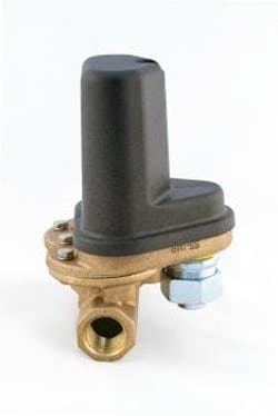
0.12 to 8.0 GPM
Detects and Signals Flow Change
- Superior Long Term Performance
- Continuous Adjustment While Operating
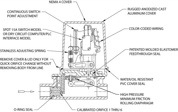
- 6 Interchangeable orifices plus 2:1 cont. Switch adj. each orifice.
- Line Pressure to 300 psig
- Temperature 180°F Continuous
- Calibrated Independent of Line Pressure and Temperature
- Maintains Calibration Limits when Subjected to Reasonable Line Hydraulic Hammer or Surge Pulses
- SPDT 15 amp switching capacity model or Dry Circuit Computer/PLC Interface model
- Intrinsically Safe Relay Allows Model Q-1 to be used in Hazardous Area (see here).
- Maintenance and checkout is a snap for your present personnel using an uncomplicated standard test meter.
Typical Working Fluids
Monitoring flow of coolant water and fluids supplied to:
- Alcohols
- Contaminated Ground Water
- Filtered Sewage Water
- Glycols
- Oils
- Pure Water
- Soap Solutions
- Tap Water
Typical Uses
- Air Condition Systems
- Brakes and Clutches
- Computer Systems
- Diffusion Vacuum Pumps
- Diodes, SCRs, Triacs, etc.
- Electro Magnets
- High Power Transistors
- Marine and Stationary Engines
- Oil Supplied to Large Bearing and Gear Systems
- Plastic Molding Equipment
- RF and Radar Transmitter
- Spotwelders
- Transformers
- Vacuum Systems
In Chemical Processing
- Fluid Blending Systems
- Heat Transfer Fluids
- Liquid Scrubbers
- Liquid Transfer
- Monitor Filter Clogging
- On/Off Control of Chemical Feed Pumps
- Starting Back-up Pumps
- Water Treatment
Flow Range – Water Calibrated at 70°F
| Orifice # | Continuous Switch Point Adjustment Range GPM | Note |
|---|---|---|
| 1 | 0.12 to 0.25 | Maximum recommended flow rate for each orifice is 4x upper-end of adjustment range. |
| 2 | 0.25 to 0.50 | |
| 3 | 0.50 to 1.0 | |
| 4 | 1.0 to 2.0 | |
| 5 | 2.0 to 4.0 | |
| 6 | 4.0 to 8.0 |
Hysteresis (% Flow Change to Activate/Deactivate Switch)
- ?5% at upper end of flow range
- ?25% at lower end of flow range
Differential pressure drops across unit (Normal Operating Conditions)
- ?1.0 psi at lower end of flow range
- ?5.0 psi at upper end of flow range
Working Line Pressure
- 300 psig max. @ 180°F Max
- (Proof tested to 1200 psig @ 180°F)
Materials
Brass body, Noryl, stainless steel, and plastic hardware. Working fluid “sees” red brass, 316 stainless steel, phosphor bronze, Noryl, and EPDM elastomer seal. (Hypalon and Viton Elastomer Seals are available on special order.)
Electrical Switch Characteristics
- SPDT
- 15 amp, 1/2 hp @ 125 or 250 VAC
- 1/2 amp @ 125 VDC, 1/4 amp @ 250 VDC
- 5 amp @ 125 VAC (tungsten lamp load)
- UL and CSA Listed
- 10,000,000 Operations Median
Model Q-1 can also be fitted with a SPDT Gold Cross Bar Switch for computer/PLC interface. Maximum Continuous Temperature: 180°F (may be extended to 200°F for short periods.)
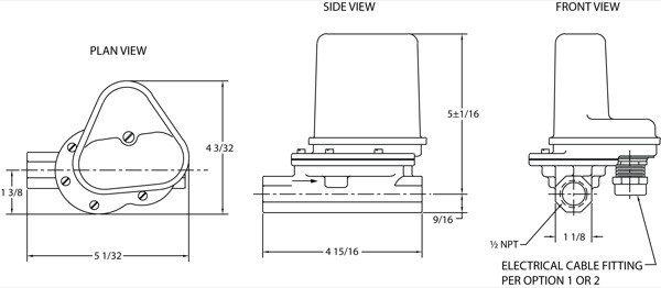
Weight: 3.5 lb.


